Example: SSD1306Demo
Frame 1
This frame shows three things:
- How to draw an XMB image
- How to draw static text which is not moved by the frame transition
- The active/inactive frame indicators
Frame 2
Currently there are one fontface with three sizes included in the library: Arial 10, 16 and 24. Once the converter is published you will be able to convert any ttf font into the used format.
Frame 3
This frame demonstrates the text alignment. The coordinates in the frame show relative to which position the texts have been rendered.
Frame 4
This shows how to use define a maximum width after which the driver automatically wraps a word to the next line. This comes in very handy if you have longer texts to display.
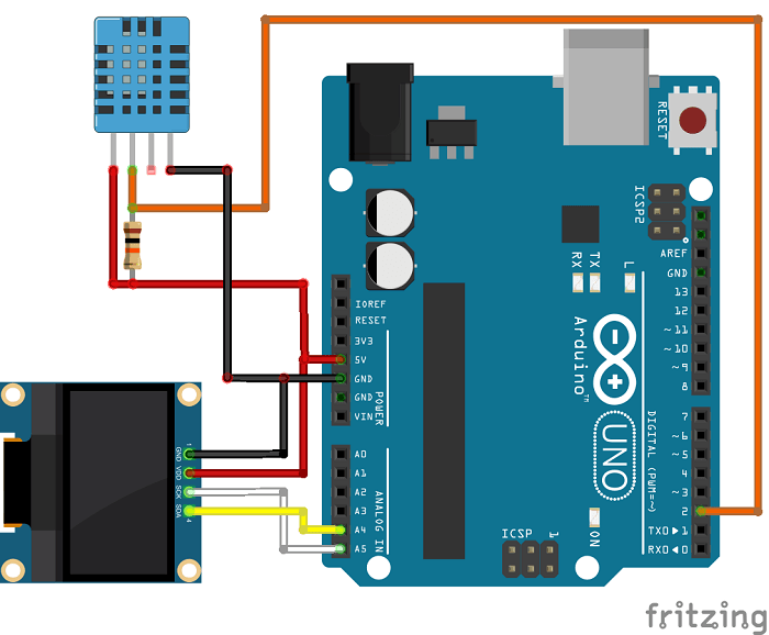
Скетч: Отображение на OLED-дисплее данных о температуре и влажности
Цель этого проекта – ознакомить вас с тем, как работает OLED-дисплей. Температура и влажность будут измеряться при помощи датчика DHT11. Если вы слышите о нем впервые, имеет смысл сначала почитать эту статью.
Подключите эти компоненты друг к другу, как показано на схеме ниже:
Код
Убедитесь, что установили обе библиотеки для управления OLED-дисплеем – «adafruit_GFX.h» и «adafruit_SSD1306.h». Кроме того, вам понадобится библиотека «DHT».
Установка библиотеки «DHT»
- Распакуйте этот архив. В итоге у вас должна получиться папка под названием «DHT-sensor-library-master».
- Переименуйте ее на «DHT_sensor_library».
- Переместите папку «DHT_sensor_library» в папку «libraries» IDE Arduino.
- Перезапустите IDE Arduino
Затем загрузите на Arduino код, показанный ниже:
 1 /*
 2  * Автор – Руи Сантос (Rui Santos)
 3  * Более подробно о проекте на: http://randomnerdtutorials.com
 4  */
 5
 6 #include <Wire.h>
 7 #include <Adafruit_GFX.h>
 8 #include <Adafruit_SSD1306.h>
 9 #include <DHT.h>
10
11 #define DHTPIN 2     // контакт, к которому подключаемся
12 #define DHTTYPE DHT11   // для датчика DHT11
13 #define OLED_RESET 4
14 Adafruit_SSD1306 display(OLED_RESET);
15
16 // создаем экземпляр класса для датчика DHT11:
17 DHT dht(DHTPIN, DHTTYPE);
18
19 void setup()
20 {
21   Wire.begin();
22   dht.begin(); // инициализируем объект «dht»
23   display.begin(SSD1306_SWITCHCAPVCC, 0x3C);
24   // инициализируем объект «display» с I2C-адресом «0x3C», для 128x32
25   Serial.begin(9600);
26 }
27 void displayTempHumid(){
28   delay(2000);
29   // считывание данных о температуре и влажности
30   // занимает около 250 мс; кроме того, это считывание
31   // может запаздывать примерно на 2 секунды
32   // (это очень медленный датчик):
33   float h = dht.readHumidity();
34   // считываем температуру в градусах Цельсия:
35   float t = dht.readTemperature();
36   // считываем температуру в градусах Фаренгейта:
37   float f = dht.readTemperature(true);
38
39   // проверяем, корректны ли данные, и если нет,
40   // то выходим и пробуем снова:
41   if (isnan(h) || isnan(t) || isnan(f)) {
42     display.clearDisplay();  //  очищаем дисплей
43     display.setTextColor(WHITE);  //  задаем цвет
44     display.setTextSize(1);  //  задаем шрифт
45     display.setCursor(5,);  //  задаем координаты курсора
46     display.print("Failed to read from DHT sensor!");
47     //  "Не удалось прочесть данные с датчика DHT!"
48     return;
49   }
50   display.clearDisplay();
51   display.setTextColor(WHITE);
52   display.setTextSize(1);
53   display.setCursor(,);
54   display.print("Humidity: ");  //  "Влажность: "
55   display.print(h);
56   display.print(" %\t");
57   display.setCursor(,10);
58   display.print("Temperature: ");  //  "Температура: "
59   display.print(t);
60   display.print(" C");
61   display.setCursor(,20);
62   display.print("Temperature: ");  //  "Температура: "
63   display.print(f);
64   display.print(" F");
65 }
66 void loop()
67 {
68   displayTempHumid();
69   display.display();
70 }
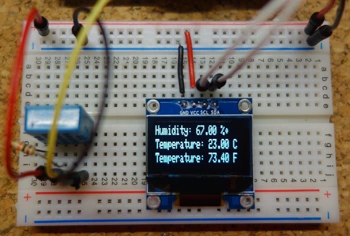
После загрузки кода OLED-дисплей начнет работать следующим образом:
Using Adafruit GFX
The SSD1306 displays are programmed using the Adafruit GFX graphics library. The easiest way is to use the Display Generator, but some of the more common commands include:
Displaying
With the SSD1306 you typically follow the pattern of:
Note that all of the commands below just write to the bitmap stored in RAM. The bitmap is not transferred to the display until you call . You probably want to do all of your drawing then call once, since it’s relatively slow to transfer the image to the display.
Fonts
There are a large number of available fonts. They’re bitmaps, so they’re specific to a particular size, but you can scale it 2x, 3x, … to make larger text, though it will be pixellated. You’ll probably want to minimize the number of fonts each font uses your code flash space. Larger fonts use more space.
In order to use a font you use setFont. You also need to include the font definition by including a specific header file. For example:
To set the font, you use:
To change the font scaling you use . The value of 1 is the normal size of the font, 2 is twice the size (each pixel is output as 2×2), 3 is three times the size (each pixel is output as 3×3), ….
Passing NULL or omitting the parameter to restores the default font.
Text
To draw text you position the cursor using and use or .
The command prints text at the current cursor position and moves the cursor to after the text. You can use multiple prints to print things left to right.
The command prints text at the current cursor position and moves the cursor to the beginning of the next line.
You can pass string constants, variables, and things you’d normally be able to pass to a String or Serial print command:
You can pass string constants and things that can be converted to a C string to print and println.
You can print a single character, a string constant or a char variable.
Passing an unsigned char or uint8_t treats the value as a number. By default, it prints in decimal (0-255). It can also be printed as hexadecimal (0-FF), octal (0-277), or binary (00000000-11111111).
Other types, both signed and unsigned, can also be printed as a number. If you pass an integer numeric constant it’s treated as int.
If you pass a double (or float), it’s printed as a decimal number. The second parameter is the number of decimal places to show, the default is 2.
Shapes
Draw a single pixel. With the SSD1306 you will almost always pass 1 for color (white).
The exception is when you’ve painted an area white, and then want to restore some pixels to black, then use color 0 (black).
Note that even when you’re using blue or yellow displays, you still use color 1 (white).
The display is coordinate (0, 0) at the upper left and (128, 64) or (128, 32) in the lower right corner depending on the display used.
Draw a line from (x0, y0) to (x1, y1).
Draw a rectangle (border only) or filled rectangle. You specify (x, y) of the upper-left and then the width and height.
Draw a rectangle with rounded corners. You specify (x, y) of the upper-left, the width and height, and the radius of the rounded corners.
Draw a circle with (x0, y0) in the center and radius (r).
Draw a triangle with corners (x0, y0), (x1, y1), and (x2, y2).
Bitmaps
The easiest way to convert a bitmap is to use the DisplayGenerator, above.
To draw a bitmap, you need the (x, y) of the upper-left, width and height (w, h) and the bitmap data.
◆ ssd1306_setRamBlock
| #define ssd1306_setRamBlock ssd1306_lcd.set_block |
Sets block in RAM of lcd display controller to write data to.
Sets block in RAM of lcd display controller to write data to. For ssd1306 it uses horizontal addressing mode, while for sh1106 the function uses page addressing mode. Width can be specified as 0, thus the library will set the right boundary to region of RAM block to the right column of the display.
- Parameters
-
x — column (left region) y — page (top page of the block) w — width of the block in pixels to control
- Use ssd1306_lcd.set_block() instead.
- Warning
- — this function initiates session (i2c or spi) and do not close it. To close session, please, use ssd1306_intf.stop().
Definition at line of file lcd_common.h.
OLED дисплей 0.91″ 128×32, I2C, SSD1306 синий
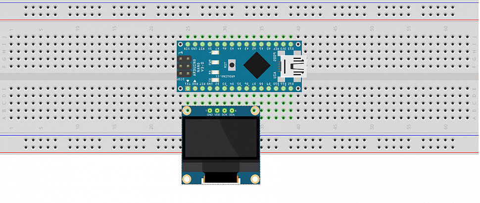
Подключение OLED дисплея I2C к NANO и вывод Русского шрифта:
https://youtube.com/watch?v=BVPY6-X_1hg
А теперь более подробно, что мы делали.
Мы использовали:
4. Библиотека с поддержкой русского и украинского языка OLED I2C
Дисплей подключаем к ARDUINO NANO по следующей схеме:
Вход питания дисплея VDD можно было бы подключить к 3,3V или 5V ARDUINO, но у нас задача обойтись без проводов. Поэтому мы установим цифровому порту ARDUINO «D2» значение HIGHT, это значит, что на pin «D2» ARDUINO подаст 5 вольт. Для сборки используем макетную плату:
Наш Скетч:
Устанавливаем библиотеку OLED_I2C (если не была установлена) и компилируем. Каждая строка в скетче подробно описана:
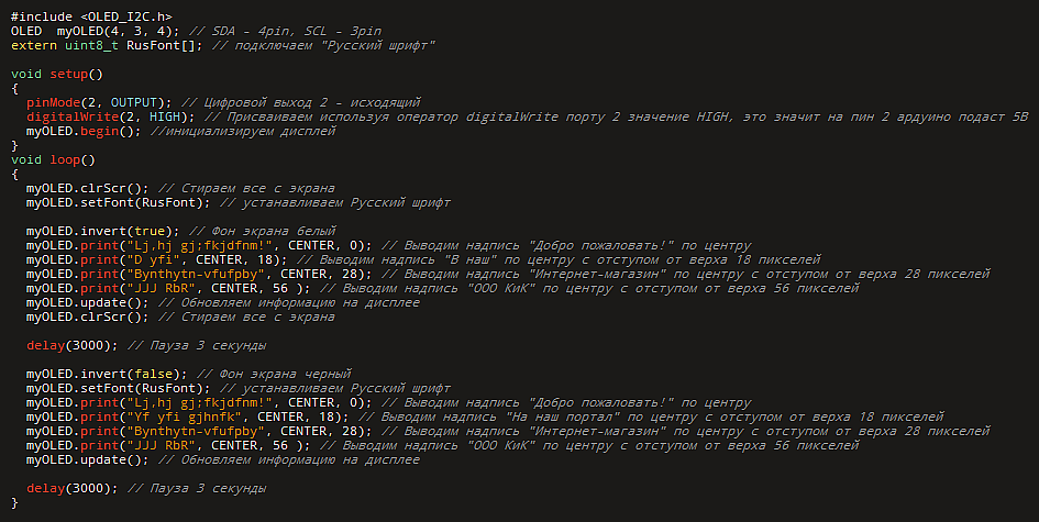
Таблица соответствия символов:
Многие, наверное, знают о таких маленьких дешёвых (меньше $3) OLED дисплеях, которые можно найти в огромном ассортименте на ebay или aliexpress. В интернете существует множество различных статей о том, как подключать эти дисплеи к Arduino и другим МК, но для STM32f10x затруднительно найти даже библиотеку. Поэтому я решил написать эту статью.
Данный дисплей имеет разрешение 128х64 пиксела и контроллер SSD1306 и подклчается к микроконтроллеру по интерфейсу I2C.
Для STM32 была найдена библиотека для этого дисплея, но она была для серии f4xx — необходимо было модифицировать для f10x.
Исходные файлы модифицированной мной библиотеки можно взять тут.
| ssd1306_i2c.c ssd1306_i2c.h | Интерфейс для работы с I2C |
| ssd1306.c ssd1306.h | Библиотека для работы с дисплеем. Представляет методы для рисования на дисплее, вывода текста, и вывода всего на oled. |
| fonts.c fonts.h | Шрифты для вывода текста на экран. Там есть три шрифта, но можно создать любой свой при помощи этой программы или аналогов |
Схема подключения предельно проста:
| Vcc | +3.3V. Допустимое напряжение — от 3.3В до 5В |
| GND | GND |
| SCL | PB6 |
| SDA | PB7 |
Для работы с библиотекой нужно подключить заголовочный файл:
И перед использованием инициализировать:
Теперь можно что-нибудь нарисовать:
Всё, что мы нарисовали сейчас находится в буффере в оперативной памяти МК, чтобы вывести всё на дисплей необходимо вызвать:
После этого наш дисплей обновится и будет выводить надпись и кружок. После вызова SSD1306_UpdateScreen() буффер в МК не сбрасывается сам, поэтому новые рисунки будут поверх предыдущих, для сброса можно заполнить всё чёрным цветом:
Все функции библиотеки:
Доступные шрифты, но вы так же можете добавить свои, в том числе и русские:
- Font_7x10
- Font_11x18
- Font_16x26
Дисплей работает довольно быстро(FPS около 14-18) на скорости I2C 400кГц(450 тоже без проблем, но рисковать не стал, а на 500 подтормаживает) и без проблем.
Использовал CooCox IDE. Готовый проект можно скачать тут: Яндекс.Диск.
P.S. с момента написания статьи и до её публикации из песочницы прошло довольно много времени(6 месяцев), за которое я успел несколько раз изменить библиотеку.
Более новую версию библиотеки с поддержкой DMA и тестовый проект для Keil и cubeMx можно взять здесь. Самую последнюю версию библиотеки вы найдёте тут.
Пример работы библиотеки:
https://youtube.com/watch?v=W4y2GvxkLcg
С удовольствием отвечу на ваши вопросы! Удачи!
Features
- Draw pixels at given coordinates
- Draw lines from given coordinates to given coordinates
- Draw or fill a rectangle with given dimensions
- Draw Text at given coordinates:
- Define Alignment: Left, Right and Center
- Set the Fontface you want to use (see section Fonts below)
- Limit the width of the text by an amount of pixels. Before this widths will be reached, the renderer will wrap the text to a new line if possible
- Display content in automatically side scrolling carousel
- Define transition cycles
- Define how long one frame will be displayed
- Draw the different frames in callback methods
- One indicator per frame will be automatically displayed. The active frame will be displayed from inactive once
◆ CONTROLLER_NATIVE_SPI_BLOCK_8BIT_CMDS
| #define CONTROLLER_NATIVE_SPI_BLOCK_8BIT_CMDS | ( | column_cmd, | |
| row_cmd | |||
| ) |
Value:
static void set_block_native(lcduint_t x, lcduint_t y, lcduint_t w) \
{ \
uint8_t rx = w ? (x + w — 1) : (. — 1); \
ssd1306_intf.start(); \
ssd1306_spiDataMode(0); \
ssd1306_intf.send(column_cmd); \
ssd1306_intf.send(x); \
ssd1306_intf.send(rx < . ? rx : (. — 1)); \
ssd1306_intf.send(row_cmd); \
ssd1306_intf.send(y); \
ssd1306_intf.send(. — 1); \
ssd1306_spiDataMode(1); \
} \
static void next_page_native(void) \
{ \
} \
ssd1306_lcd_t ssd1306_lcd
Definition:
lcduint_t height
Definition:
lcduint_t width
Definition:
Macro generates 2 static functions, applicable for many oled controllers with 8-bit commands: set_block_native(), next_page_native(). These functions are to be used when working in oled controller native mode.
- Parameters
-
column_cmd command opcode for setting column address according to oled controller datasheet row_cmd command opcode for setting row address according to oled controller datasheet
- Note
- It is assumed that column and row commands accept 2 single byte arguments: start and end of region
Definition at line of file lcd_common.h.
Running the Adafruit Example Sketch
If the libraries for the display were installed correctly, example programs for the display will be found in the Arduino IDE under File → Examples → Adafruit SSD1306 – open the ssd1306_128x64_i2c sketch under this menu.
The I²C address must be changed in this sketch in order for it to work with the Geekcreit display. Change the address from 0x3D to 0x3C as shown in the code below. This address is not 0x78 or 0x7A as printed on the back of the OLED board.
void setup()   {
  Serial.begin(9600);

  // by default, we'll generate the high voltage from the 3.3v line internally! (neat!)
  //display.begin(SSD1306_SWITCHCAPVCC, 0x3D);  // initialize with the I2C addr 0x3D (for the 128x64)
  display.begin(SSD1306_SWITCHCAPVCC, 0x3C);  // changed this to 0x3C to make it work
  // init done
As shown above, the address was changed to 0x3C in display.begin(). The original line of code is shown above it and is commented out.
After making the changes, the sketch can be uploaded to the Arduino. When building the sketch for an Arduino Uno the IDE will display a low memory warning message, but the sketch will still run.
If the changes to the driver and example sketch were made correctly and the OLED display is wired to the Arduino correctly, the sketch should start running. The example program starts by showing the Adafruit logo, it then turns on a single pixel. Various graphics and text functions are then displayed.
You can help the Starting Electronics website by making a donation:
Any donation is much appreciated and used to pay the running costs of this website. Click the button below to make a donation.
Arduino OLED I²C Libraries for SSD1306 and Graphics Functions
Two Arduino libraries must be installed to start using the display. The SSD1306 driver library is used to initialize the display and provide low level display functions. The GFX library provides graphics functions for displaying text, drawing lines and circles, etc. Both these libraries are available from Adafruit.
Install the SSD1306 Driver Library
Download the Adafruit_SSD1306 library which is saved to your computer in a file called Adafruit_SSD1306-master.zip.
Copy the Adafruit_SSD1306-master folder from the downloaded zipped file into the Arduino libraries folder. This folder is usually found at Documents → Arduino → libraries on Windows systems. On Linux it is usually found at home folder → Arduino → libraries.
Finally in the Arduino library folder, rename the Adafruit_SSD1306-master folder to Adafruit_SSD1306.
Install the GFX Library
Download the Adafruit_GFX library which is saved to your computer in a file called Adafruit-GFX-Library-master.zip.
Copy the Adafruit-GFX-Library-master folder from the downloaded zipped file to the Arduino library folder as done for the SSD1306 driver above.
In the Arduino library folder rename the Adafruit-GFX-Library-master folder to Adafruit_GFX.
Verifying the Library Installation
After installing the libraries, your Arduino library folder should look as follows.
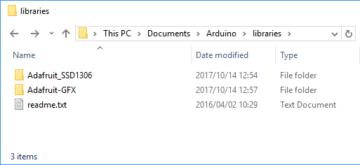
Arduino Library Folder with New Libraries Installed
The contents of the two library folders should look as follows, with the SSD1306 driver library folder on the left and GFX library on the right.
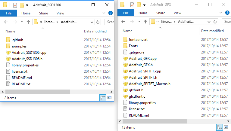
Adafruit SSD1306 and GFX Library Folders
Finding the OLED Libraries in Arduino
If the Arduino IDE was open during the library installation, close it first and then restart it.
In the Arduino IDE, find the libraries under the Sketch → Include Library menu from the top menu bar. When the mouse cursor is hovered above the Include Library menu item, the new libraries can be found on the pop-out menu. In Windows the libraries appeared under «Contributed libraries» near the top of the pop-out menu on my system. On my Linux computer the libraries appeared under the «Recommended libraries» section of the pop-out menu near the bottom.
Modifying the SSD1306 Driver
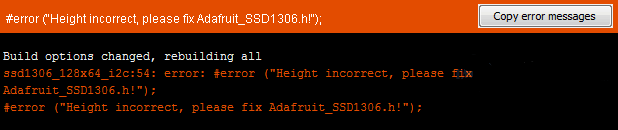
The SSD1306 driver isn’t set up for the Geekcreit OLED display by default. The display size must be changed in the driver before it can be used. If it is not changed, an error message will appear when attempting to verify the example sketch (see the section below) in the Arduino IDE:#error («Height incorrect, please fix Adafruit_SSD1306.h!»);
Open the Adafruit_SSD1306 folder that was just installed in the Arduino libraries folder. Find Adafruit_SSD1306.h and open it in a text editor. Scroll down the file to find the section with the header SSD1306 Displays or search for for this term in the text editor to find it quickly. Comment out #define SSD1306_128_32 and uncomment #define SSD1306_128_64 so that the code in this section looks as follows.
/*=========================================================================
    SSD1306 Displays
    -----------------------------------------------------------------------
    The driver is used in multiple displays (128x64, 128x32, etc.).
    Select the appropriate display below to create an appropriately
    sized framebuffer, etc.

    SSD1306_128_64  128x64 pixel display

    SSD1306_128_32  128x32 pixel display

    SSD1306_96_16

    -----------------------------------------------------------------------*/
   #define SSD1306_128_64
//   #define SSD1306_128_32
//   #define SSD1306_96_16
/*=========================================================================*/
Save the file after making the changes.
Объяснение программы для Raspberry Pi
Полный код программы приведен в конце статьи, здесь же мы кратко рассмотрим его основные фрагменты.
Первым делом в программе мы подключим (импортируем) необходимые нам библиотеки.
Python
import time
import Adafruit_GPIO.SPI as SPI
import Adafruit_SSD1306
from PIL import Image
from PIL import ImageDraw
from PIL import ImageFont
import subprocess
|
1 |
importtime importAdafruit_GPIO.SPI asSPI importAdafruit_SSD1306 fromPIL importImage fromPIL importImageDraw fromPIL importImageFont importsubprocess |
После этого инициализируем дисплей.
Python
RST = 0
disp = Adafruit_SSD1306.SSD1306_128_64(rst=RST)
disp.begin()
disp.clear()
disp.display()
width = disp.width
height = disp.height
image1 = Image.new(‘1’, (width, height))
draw = ImageDraw.Draw(image1)
draw.rectangle((0,0,width,height), outline=0, fill=0)
padding = -2
top = padding
bottom = height-padding
x = 0
font = ImageFont.load_default()
|
1 |
RST= disp=Adafruit_SSD1306.SSD1306_128_64(rst=RST) disp.begin() disp.clear() disp.display() width=disp.width height=disp.height image1=Image.new(‘1’,(width,height)) draw=ImageDraw.Draw(image1) draw.rectangle((,,width,height),outline=,fill=) padding=-2 top=padding bottom=height-padding x= font=ImageFont.load_default() |
После этого мы сможем передавать данные или изображения на OLED дисплей с помощью следующего фрагмента кода:
Python
# Write two lines of text.
disp.clear()
disp.display()
draw.text((x, top), «OLED Interfacing » , font=font, fill=255)
draw.text((x, top+8), «Circuit Digest», font=font, fill=255)
draw.text((x, top+16), «For more Videos», font=font, fill=255)
draw.text((x, top+25), «Visit at», font=font, fill=255)
draw.text((x, top+34), «www.circuitdigest.com», font=font, fill=255)
# Display image.
disp.image(image1)
disp.display()
time.sleep(2)
if disp.height == 64:
image = Image.open(‘img1.png’).convert(‘1’)
else:
image = Image.open(‘img1.png’).convert(‘1’)
disp.image(image)
disp.display()
time.sleep(2)
if disp.height == 64:
image = Image.open(‘img3.jpg’).convert(‘1’)
else:
image = Image.open(‘img3.jpg’).convert(‘1’)
|
1 |
# Write two lines of text. disp.clear() disp.display() draw.text((x,top),»OLED Interfacing «,font=font,fill=255) draw.text((x,top+8),»Circuit Digest»,font=font,fill=255) draw.text((x,top+16),»For more Videos»,font=font,fill=255) draw.text((x,top+25),»Visit at»,font=font,fill=255) draw.text((x,top+34),»www.circuitdigest.com»,font=font,fill=255) disp.image(image1) disp.display() time.sleep(2) ifdisp.height==64 image=Image.open(‘img1.png’).convert(‘1’) else image=Image.open(‘img1.png’).convert(‘1’) disp.image(image) disp.display() time.sleep(2) ifdisp.height==64 image=Image.open(‘img3.jpg’).convert(‘1’) else image=Image.open(‘img3.jpg’).convert(‘1’) |
Используемый нами OLED дисплей выпускается в двух вариантах, с разрешением 128*32 и 128*64. Необходимое разрешение вы можете выбрать при инициализации дисплея. К примеру, для инициализации дисплея с разрешением 128*64 необходимо использовать следующую команду:
Python
disp = Adafruit_SSD1306.SSD1306_128_64(rst=RST)
| 1 | disp=Adafruit_SSD1306.SSD1306_128_64(rst=RST) |
Используемый далее код программы достаточно прост и, на наш взгляд, не нуждается в дополнительных пояснениях. Вы можете поэкспериментировать в нем с изменением ширины и высоты изображений и попробовать запрограммировать другие функции для вывода на экран дисплея «крутых» геометрических фигур.
Features
- Draw pixels at given coordinates
- Draw lines from given coordinates to given coordinates
- Draw or fill a rectangle with given dimensions
- Draw Text at given coordinates:
- Define Alignment: Left, Right and Center
- Set the Fontface you want to use (see section Fonts below)
- Limit the width of the text by an amount of pixels. Before this widths will be reached, the renderer will wrap the text to a new line if possible
- Display content in automatically side scrolling carousel
- Define transition cycles
- Define how long one frame will be displayed
- Draw the different frames in callback methods
- One indicator per frame will be automatically displayed. The active frame will be displayed from inactive once
◆ ssd1306_printFixed()
| uint8_t ssd1306_printFixed | ( | uint8_t | xpos, |
| uint8_t | y, | ||
| const char * | ch, | ||
| style | |||
| ) |
Prints text to screen using fixed font.
- Parameters
-
xpos — horizontal position in pixels y — vertical position in pixels ch — NULL-terminated string to print style — font style (EFontStyle), normal by default.
- Returns
- number of chars in string
- See also
- Warning
- can output chars at fixed y positions: 0, 8, 16, 24, 32, etc. If you specify , will output text starting at position.
- Be careful with you flash space! Do not mix too many different functions in single sketch. uses much flash: ~396 bytes, needs 388 bytes. Placing both of these functions to your sketch will consume almost 1KiB.
Definition at line of file ssd1306_1bit.c.
SPECIFICATIONS
Interface Pin Function
| No. | Symbol | Function |
|---|---|---|
| 1 | SDA | When serial interface mode is selected, D0 will be the serial clock input: SCLK; D1 will be the serial data input: SDIN. When I2C mode is selected, D2, D1 should be tied together and serve as SDAout, SDAin in application and D0 is the serial clock input, SCL. |
| 2 | SCL | |
| 3 | SA0 | In I2C mode, this pin acts as SA0 for slave address selection. When 3-wire serial interface is selected, this pin must be connected to VSS. |
| 4 | RST | This pin is reset signal input. When the pin is pulled LOW, initialization of the chip is executed. Keep this pin HIGH (i.e. connect to VDD) during normal operation. |
| 5 | CS | This pin is the chip select input. (active LOW). |
| 6 | VDD | 3.0V Power supply pin for core logic operation. |
| 7 | VIN | 5.0V Power supply pin for core logic operation. |
| 8 | GND | This is a ground pin. |
Mechanical Data
| Item | Dimension | Unit |
|---|---|---|
| Dot Matrix | 128 × 64 | Dots |
| Module dimension | 38.00 × 28.50 × 2.37 | mm |
| Active Area | 21.74 × 10.86 | mm |
| Pixel Size | 0.148 × 0.148 | mm |
| Pixel Pitch | 0.17 × 0.17 | mm |
| Display Mode | Passive Matrix | |
| Display Color | Monochrome | |
| Drive Duty | 1/64 Duty | |
| IC | SSD1306 | |
| Interface | I2C, SPI | |
| Size | 0.96 inch |
Absolute Maximum Ratings
| Parameter | Symbol | Min | Max | Unit |
|---|---|---|---|---|
| Supply Voltage for Logic | VDD | 1.65 | 3.3 | V |
| Supply Voltage for Logic | VIN | 4.0 | 6.0 | V |
| Operating Temperature | TOP | -40 | +80 | °C |
| Storage Temperature | TSTG | -40 | +85 | °C |
Electronical Characteristics
| Item | Symbol | Condition | Min | Typ | Max | Unit |
|---|---|---|---|---|---|---|
| Supply Voltage for Logic(3V) | VDD | - | 2.8 | 3.0 | 3.2 | V |
| Supply Voltage for Logic(5V) | VIN | - | 4.8 | 5.0 | 5.2 | V |
| Input High Volt. | VIH | - | 0.8×VDD | - | VDDIO | V |
| Input Low Volt. | VIL | - | - | 0.2×VDD | V | |
| Output High Volt. | VOH | - | 0.9×VDD | - | VDDIO | V |
| Output Low Volt. | VOL | - | - | 0.1×VDD | V | |
| 50% Check Board operating Current | ICC | Vcc=7.5V | - | 12.0 | 22.0 | mA |
Search keyword: 128×64 oled, oled 128×64, 0.96″ oled, 0.96 inch oled, oled 0.96″,12864 oled, oled 12864,oled 128×64 spi,oled 128×64 ssd1306
Модификация библиотеки Adafruit SSD1306
Библиотека Adafruit SSD1306 не настроена для 128 × 64 OLED-дисплеев (используемый в данной статье). Размер экрана необходимо изменить в заголовочном файле Adafruit_SSD1306.h.
Если этого не сделать, то при компиляции мы получим сообщение об ошибке #error (“Height incorrect, please fix Adafruit_SSD1306.h!”):
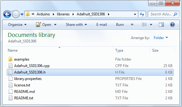
Чтобы изменить заголовочный файл Adafruit_SSD1306.h, откройте Документы > Arduino. Теперь перейдите в библиотеку Adafruit_SSD1306:
Откройте файл Adafruit_SSD1306.h в текстовом редакторе (например, notepad++). Прокрутите файл вниз, чтобы найти раздел с дисплеями SSD1306 или сразу перейдите к строке №73. Закомментируйте #define SSD1306_128_32 и раскомментируйте #define SSD1306_128_64, чтобы код в этом разделе выглядел следующим образом:
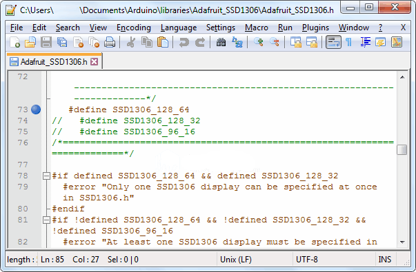
Вот и все. Теперь сохраните файл и перезапустите вашу Arduino IDE.
Example: SSD1306Demo
Frame 1
This frame shows three things:
- How to draw an xbm image
- How to draw a static text which is not moved by the frame transition
- The active/inactive frame indicators
Frame 2
Currently there are one fontface with three sizes included in the library: Arial 10, 16 and 24. Once the converter is published you will be able to convert any ttf font into the used format.
Frame 3
This frame demonstrates the text alignment. The coordinates in the frame show relative to which position the texts have been rendered.
Frame 4
This shows how to use define a maximum width after which the driver automatically wraps a word to the next line. This comes in very handy if you have longer texts to display.
Pixel drawing
/* Drawing functions */
// Sets the color of all pixel operations
void setColor(OLEDDISPLAY_COLOR color);

// Draw a pixel at given position
void setPixel(int16_t x, int16_t y);

// Draw a line from position 0 to position 1
void drawLine(int16_t x0, int16_t y0, int16_t x1, int16_t y1);

// Draw the border of a rectangle at the given location
void drawRect(int16_t x, int16_t y, int16_t width, int16_t height);

// Fill the rectangle
void fillRect(int16_t x, int16_t y, int16_t width, int16_t height);

// Draw the border of a circle
void drawCircle(int16_t x, int16_t y, int16_t radius);

// Fill circle
void fillCircle(int16_t x, int16_t y, int16_t radius);

// Draw a line horizontally
void drawHorizontalLine(int16_t x, int16_t y, int16_t length);

// Draw a lin vertically
void drawVerticalLine(int16_t x, int16_t y, int16_t length);

// Draws a rounded progress bar with the outer dimensions given by width and height. Progress is
// a unsigned byte value between 0 and 100
void drawProgressBar(uint16_t x, uint16_t y, uint16_t width, uint16_t height, uint8_t progress);

// Draw a bitmap in the internal image format
void drawFastImage(int16_t x, int16_t y, int16_t width, int16_t height, const char *image);

// Draw a XBM
void drawXbm(int16_t x, int16_t y, int16_t width, int16_t height, const char* xbm);
Introduction
The objective of this post is to explain how we can change the value of a string drawn in the SSD1306 OLED display, using the Arduino core running on the ESP32.
To illustrate how to do it, we will show a simple counter that will be incremented every second.
You can check how to wire the ESP32 to the SSD1306 OLED display and how to install the library needed to interact with it on this previous post.
For this tutorial, an Elecrow’s version of the SSD1306 OLED display was used. The ESP32 board used was a NodeMCU.
The code
We will start the code by including the Wire.h library, which is needed to interact with the display via I2C. We will also include the SSD1306.h library, which exposes the functionality needed to draw on the display.
#include <Wire.h>
#include "SSD1306.h"
Next we will create an object of class SSD1306, which has the methods we are going to use to draw on the display.
Remember from the previous post that the constructor for this class receives as first input the I2C address of the display and as second and third inputs the numbers of the I2C SDA and SCL pins, respectively.
In our case, we will keep using the connection diagram shown on the previous post, so the SDA pin will be 21 and the SCL will be the 22.
SSD1306 display(0x3c, 21, 22);
We will also declare our counter as a global variable, so we can later increment it on the multiple iterations of the Arduino loop function.
int counter = 0;
Moving on to the setup function, we will initialize the display with a call to the init method on our display object.
void setup() {
  display.init();
}
Since we want to dynamically change the content of the string that is going to be shown on the display, we will do the remaining code on the Arduino loop function.
Since in each iteration of the loop we will be displaying new content, we first clear the display with a call to the clear method. This method receives no arguments and returns void.
display.clear();
Then we write the string we want to display with a call to the drawString method on our display object.
We will keep the coordinates where the string will be drawn at zero (the first and second parameters of the drawString method are the x and y position, respectively).
As third argument, we will pass the string to be drawn, which will be built from our global counter.
display.drawString(0,0, "Counter: " + String(counter));
Next, in order to send the actual content to be drawn on the display, we call the display method on our object.
display.display();
To finalize the Arduino loop, we will increment the counter and perform a small 1 second delay between each iteration. Thus, the content shown in the display should refresh each second and show the new value of the counter.
counter ++;
delay(1000);
The final complete code can be seen below
#include <Wire.h>
#include "SSD1306.h"

SSD1306  display(0x3c, 21, 22);
int counter = 0;

void setup() {
  display.init();
}

void loop() {
  display.clear();
  display.drawString(0,0, "Counter: " + String(counter));
  display.display();

  counter ++;
  delay(1000);
}
Общие сведения об OLED дисплеях
OLED означает “Organic Light emitting diode“, что переводится как органический светоизлучающий диод, или, более коротко – органический светодиод. OLED дисплеи для радиолюбителей изготавливаются по той же самой технологии, что и большинство современных телевизоров, но имеют гораздо меньше пикселов по сравнению с ними. Но устройства на их основе (в том числе и с использованием Arduino) смотрятся потрясающе.
В нашем проекте мы будем использовать монохромный 7-пиновый SSD1306 0.96” OLED дисплей. Причина, по которой мы выбрали данный дисплей, заключается в том, что он может работать с тремя разными протоколами связи, трехпроводный SPI (Serial Peripheral Interface — последовательный интерфейс) режим, четырехпроводный SPI режим и режим IIC. В данной статье мы рассмотрим его подключение по четырехпроводному SPI режиму как самому скоростному из приведенных.
Контакты дисплея и выполняемые ими функции описаны в следующей таблице.
| Номер контакта | Название контакта | Альтернативное название контакта | Назначение контакта |
| 1 | Gnd | Ground | земля |
| 2 | Vdd | Vcc, 5V | напряжение питания (в диапазоне 3-5 В) |
| 3 | SCK | D0, SCL, CLK | контакт синхронизации (clock pin). Применяется в интерфейсах I2C и SPI |
| 4 | SDA | D1, MOSI | контакт данных. Применяется в интерфейсах I2C и SPI |
| 5 | RES | RST, RESET | контакт сброса модуля. Применяется в интерфейсе SPI |
| 6 | DC | A0 | контакт команд (Data Command pin). Применяется в интерфейсе SPI |
| 7 | CS | Chip Select (выбор чипа) | используется когда несколько устройств взаимодействуют по интерфейсу SPI |
Сообществом Arduino разработано достаточно много библиотек для работы с подобными дисплеями. Мы выбрали из них библиотеку Adafruit_SSD1306 как весьма простую и в то же время содержащую достаточно много полезных функций. Но если ваш проект имеет жесткие ограничения по памяти/скорости, то тогда вам лучше использовать библиотеку U8g поскольку она работает быстрее и занимает меньше места в памяти.
Похожие записи:
 Смешарики своими руками: делаем вязаные крючком, шитые, сделанные из пластилина, шаров и конфет
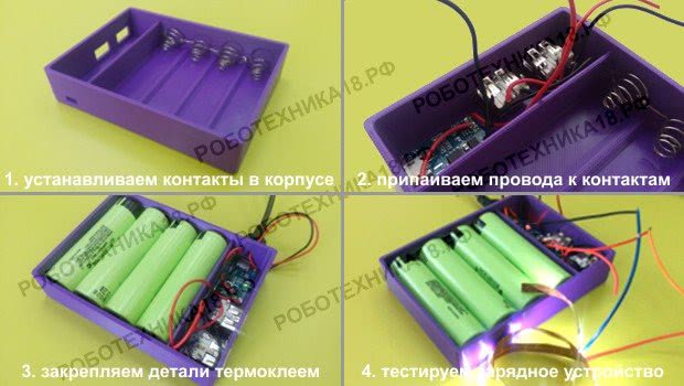 Как сделать повер банк своими руками
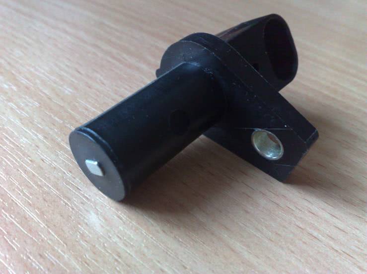 Как вынуть провода из соединительной колодки (фишки) электропроводки автомобиля
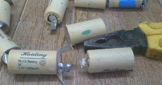 Восстановление аккумулятора шуруповерта
 Изготовление оригинальной ручки для двери
 Противоугонка для прицепа: выбираем лучшее устройство